During the 1960s and early 1970s many large
hydrogen-cooled generators
of 500 MW and upwards with water-cooled stator windings were
brought
into service. A number of these machines - irrespective of
manufacturer
- exhibited core end heating problems. [Tavner
& Anderson Nov 2005]
- On installation of the first 500 MW generators on the CEGB system in 1968 there were some difficulties in operating at high leading power factor, there were a number of relatively serious core failures in which parts of generator cores were damaged by melting, and a few generators were found to have rather unstable end-heating problems which gave rise to long-term operational restrictions.
- A major core failure at Turkey Point No 3 (Florida Power and Light) was reported in 1968 in which molten metal had been ejected from one of the stator slots over a fault length of 17 feet and had spilled into the generator housing.
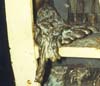 |
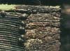
Failures like the one shown here on the left are rare. This example is notable because approximately 500 kg of coreplate had melted before conductor bar insulation was sufficiently damaged to trigger the earth leakage protection system and trip the generator. |
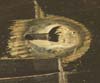
duct damage |
These notes merely reflect the author's own opinions, formed partly as a result of examining a number of machines with varying degrees of core end and back-of-core damage and several machines with extensive core fault damage during the 1970s and early 1980s, partly as a result of talking with others working in this same field and partly as a result of revisiting the subject area during recent electrical machine failure investigations. |
2. Eddy currents in the machine magnetic circuit
Eddy currents in electrical machines restrict the rate at
which flux
can change in the magnetic circuit and may cause appreciable heating
losses.
Eddy currents are normally minimised by constructing
magnetic
circuits from thin laminations punched from steel strip. These
laminations
are de-burred, cleaned and then insulated with varnish before being
assembled.
The principles of core construction for transformers and rotating
machines
are fairly similar.
spot weld |
If the insulation between adjacent laminations should break down, for instance because of mechanical damage to to a stator tooth, this will result in an increase in the local eddy currents and perhaps result in a local hotspot. Surface hotspots can usually be detected by a static ring flux test. Internal hotspots, as for example where there has been an interlaminar breakdown between lamination surfaces, are much more difficult to detect. |
3. Interlaminar breakdowns caused by foreign bodies
It is not unknown for a metallic foreign body - a nut, a bolt, a washer or a piece of swarf etc. - to find its way into the rotor/stator gap or into an axial cooling duct in the stator core. Over time this foreign body may vibrate against the lamination edges and damage the interlaminar insulation, causing adjacent laminations to come in contact with one another. This may lead to a significant number of laminations becoming connected together and therefore to a local hotspot.
The interlaminar voltage in the main part of the core is modest - typical figures for 0.35 mm laminations being of the order of 50 mV for a large two pole machine. Therefore only if the damage were to occur over sufficient laminations and if the core-to-frame contact were to be consistently good, could a runaway fault condition occur. Usually the damage - visible as a polishing of tooth surfaces - is detected during a routine inspection and, in most cases, the lamination insulation can be restored.
One method of restoration used is to etch the lamination
edges
electrolytically using phosphoric acid, clean surfaces and then apply a
penetrating epoxy resin that is drawn between the laminations by
capilliary action.
4. Interlaminar breakdowns caused by vibrating stator teeth
One of the most difficult aspects of core building is to ensure that the core is tightly and uniformly packed and that no part of an individual lamination - a stator tooth for example - is free to vibrate axially.
The main reason for poor packing is that laminations are not of uniform thickness. The steel strip from which they are punched is always thinnest at the edges and thickest in the middle. Since large lamination segments are nearly always cut so that the yoke portion is aligned with the direction of rolling, the teeth and the back of core are always thinner than the portion just below the bottom of slot. Therefore unless sufficient measures are taken to compensate for the cumulative difference of thickness during core building, or unless the core is bonded, it is likely that somewhere in the core there will be loose tooth laminations.
If these loose tooth laminations happen to be near a radial
vent duct,
they will be subject to axial forces tending to separate them from the
mass of the core. Given time, a portion of lamination may fatigue and
break
off, leaving space for the adjacent laminations to vibrate and in due
course
fatigue and break off in the same way. Eventually a whole portion of
tooth
may disappear. The broken portions may cause further damage in the same
way as any other foreign body.
5. End Region Heating due to eddy currents
Within the main active section of the magnetic circuit of a conventional type of a.c. machine the flux has radial and circumferential components. Towards each end of the core, as a result of the circumferential components of excitation current from the end windings, there will be axial flux components in the stator core which will tend to set up circulating eddy current in the plane of the laminations.
In large a.c. rotating electrical machines, the axial fluxes caused by circumferential currents flowing in the rotor and stator end windings are sufficiently great to induce significant eddy currents in the laminations at each end of the stator core and in the core clamping plates. These circumferential/radial eddy currents give high losses, particularly in the bottom of slot regions and especially in large turbine generators. because of their very high specific power outputs.
The end region losses are highest when operating far in the leading power factor region.
Various methods are used to minimise eddy current losses in the core end regions. (1) conducting screens on the core end plates to act as flux divertors (2) profiling the end of the core, i.e. locally increasing the reluctance of the rotor/stator gap (3) segmentation of the laminations (4) the use of narrow slits - "pistoye slots" - in the rotor teeth to lengthen the path taken by the eddy currents, thereby increasing the path resistance and decrease the current/losses (5)use of extra coatings of insulating varnish on the laminations. . Core end region design is therefore a compomise between keeping the eddy current losses small yet maintaining adequate magnetic, thermal and mechanical properties.
Attention to overall design would be of little effect however without equal attention to the detail: use of low-loss steel for the laminations ; maintenance of punch and die quality ; adequate deburring after punching ; cleaning after deburring ; cleanliness of the varnish insulation process ; the appropriate segmentation and lapping of laminations; careful core-building ; maintenance of adequate and uniform core pressure, both during core build and later in operation.
Even with careful attention to design, interlaminar voltage levels at the ends of cores may be as much as 40 or 50 times as high as in the main body of the core under steady state conditions and higher still under transient conditions. As a consequence, the core ends are extremely vulnerable to the slightest imperfection in interlaminar insulation.
An indication of significant core end heating having occurred
at some
time is often provided by
discolouration of varnish on the outermost laminations behind the slot.
Typically, heat discolouration contours will be visible behind most
slots
and at both ends of the machine. In addition there may be signs of more
localised overheating, for example at the butt joint positions and
sometimes
between surfaces away from lamination edges. See also the
possible
role of transients in damaging the interlaminar insulation, see
note
below.
6. Problems caused by back-of-core leakage flux
 |
An additional source of troublesome eddy currents in the stator core end regions of large machines is caused by the "back-of-core leakage flux", which is the small component of armature flux that is not contained by the core and which permeates the space behind the core and tends to be drawn into circumferential members of the core frame. The axial members of the core frame are exposed to this leakage flux and act as a squirrel cage, with the circumferential members of the core frame at the ends of the machine providing return paths. |
At least, this would be the situation were it not for the fact
that
the core is often in direct contact with the frame via the axial
keybars
which communicate the torque reaction to the core frame. Because the
laminated
core represents a lower impedance path than the frame, there is a
tendency
for the back of core currents to complete the circumferential path at
the
core ends via the core and not the frame.
 |
Conduction of back-of-core currents circumferentially via the back of core would not be a problem if the core was not subject to torque reaction and ovalising forces. The relative movement that results can cause intermittent core to keybar contacts and consequential arcing at the back of core. |
- Some manufacturers have attempted to overcome the problem by placing a copper strip between each keybar and the frame and joining these to circumferential copper strap, one at each end of the core, to form a true squirrel cage. This is on the basis that the circumferential currents will prefer the copper strip to either the core frame or the core.
- Other manufacturers have chosen to weld the keybars to the back of core in order to guarantee that the currents will always take the back of core path provided for them.
- Yet others go for a semi-insulated core with one keybar earthed to provide earth leakage protection in the event of a bar to core insulation breakdown.
In most cases, arcing at the back of core merely results in local core to frame welding and, in consequence, and in time, the whole of the core becomes well grounded and arcing will cease. However when back of core arcing takes place damage may not be confined to the back of core. The interlaminar insulation may be stressed and an interlaminar breakdown may occur as a point of weakness well away from the back of core - for instance, on a tooth, at the bottom of slot or in an axial vent duct. Given sufficient energy fed into interlaminar breakdown, this may cause significant local damage. Over time a number of these interlaminar breakdowns may occur and cause a significant rise in the core end losses.
7. Exacerbating factors 1 : The role of transient disturbances
Under transient conditions - sudden short circuit, line clashing, pole slipping etc. - the stator currents may well rise to several times their steady state value. This will not produce significant changes in the main flux because the moment that the stator flux starts to rise, eddy currents will spring up in the rotor damper winding tending to keep the flux linkages constant. However in the end regions the end winding ampere turns and the damping currents in the rotor damper winding tend to augment each other rather than cancel each other out. The result is a considerable increase both in axial flux and in the back of core leakage flux at the ends of the core. As a result the interlaminar insulation will be more highly stressed and therefore more likely to break down at points of insulation weakness.
The situation is complicated by relative vibration between core and frame which will clearly be greatest under transient conditions and will cause a greater degree of intermittent contact between the core at its ends and the core frame keybars than under steady loads.
8. Exacerbating factors 2 : interlaminar capacitance.
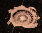
A feature of many generator cores that have been in service is the existence of small spit marks - sometimes so small that they may be missed altogether - that may be found at lamination edges in the end regions. These may be found at the back of core, on the teeth, in the slots in vent ducts and between surfaces, indeed anywhere where there might be points of insulation weakness. These turn out usually to be microscopic spot welds. Sometimes the welding extends over several laminations.
A possible explanation lies in considering the core end laminations in their pristine state to be a large parallel plate capacitor whose plates are short-circuited by the core to keybar contacts.Whenever the core to frame contacts are broken the inductive currents continue to flow into the open-circuited capacitor, giving rise to a rapid rise in voltage across the laminations. This process of capacitative charging will continue either until there is an interlaminar breakdown, when all the capacitative energy is discharged into the fault, or until the stored capacitative energy equals the initial inductive energy and the conditions for an oscillatory discharge are established.
On the basis of this argument, the better the interlaminar insulation, the bigger the build up of stored charge between the laminations before breakdown takes place and the greater the capacity for causing significant interlaminar damage.
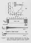
The inductive/capacitative phenomenon can be simply
demonstrated in
a controlled manner in the laboratory with two laminations connected as
the plates of a capacitor across a switch that is connected in series
with
a battery and an inductance. Opening the switch will produce a
breakdown
at the weakest point of insulation. By inserting insulation at the
point
of breakdown, and repeating the switching, a breakdown will occur
at the next weakest point : this time the flash will be slightly
brighter, and so on. Eventually the energy input will be sufficient to
cause welding at the point of breakdown.
The experiment may be varied to show, for example, the modifying effect of oil, which increases the dielectric strength at the point where breakdown formerly occurred and shifts the breakdown elsewhere.
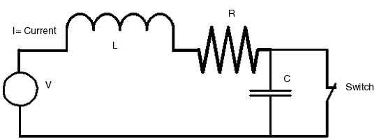 Circuit used to artificially induce
interlaminar voltages
|
Video clip demonstrations of artificially
induced interlaminar voltages
Interlaminar
voltage breakdown demo 1
Interlaminar voltage breakdown demo 2 [Copywright Antony Anderson 2007] |
9. Exacerbating factors 3 : The possible effect of hydrogen disassociation
The coolant in large generators is usually hydrogen gas, which when subject to the high temperatures of an electric arc disassociates into atomic hydrogen H, which is extremely reactive. This disassociation may provide a possible link between the localised core burning at the ends of machines - including the spitting mentioned above - and a full scale core fault.
Hydrogen arcs are localised (see Langmuir, G.E. Review XXIX No 3 152 March 1926) and are characterised by a very high rate of heat transfer which cannot be accounted for by conduction, convection or radiation. A process of disassociation takes place in which the molecule H2 is converted into atomic hydrogen H, with the absorption of heat from the arc. Subsequently the hydrogen atoms recombine in the presence of a catalyst, giving up their heat to the catalyst in the process. Metals such as iron are good catalysts and may be heated to incandescence or be melted at some distance from the arc (3-5 cm). Heat transfer rates are about 11 times greater than might be expected from Hydrogen in its molecular form. Large quantities of hydrogen gas are not required to transfer large quantities of heat. The efficiency of the heat transfer process is high (82% 3mm from a metal surface to 55% at 35mm). The energy is transferred preferentially to metal in the vicinity of the arc causing greater damage than might be expected in air.
Whilst the disassociation of hydrogen is well understood and
indeed
is exploited in the hydrogen arc welding process, it has not been
proven
definitively to be a factor in core fault propagation. Nevertheless the
core failures in large machines have involved arcing in a hydrogen
atmosphere
and therefore it is entirely logical to believe that disassociation of
hydrogen does play a part.
Discussion and Conclusions
The specific power output in a large turbogenerator is some 70 MW per metre of active length of core and the heat content of 1 gram of silicon steel at its melting point is approx 1330 J/gm. Therefore if the energy output from 1m length of core were to be diverted into a single core hotspot the core could, in theory, melt at a rate of 54 kg/second, ignoring radiation, convection and conduction losses. Core faults are known in which several hundred kg of core have been melted. It is salutory to realise that even such large scale melting may have occurred in just a few seconds.
We have seen that there are mechanisms capable of producing transiently very high interlaminar voltages and causing localised breakdowns, both in the form of spot welds or meandering breakdowns.
Furthermore it is clear that hydrogen gas, the stator coolant on large machines, can act as an extremely efficient heat transfer medium if it disassociates in the presence of an arc.
Bearing in mind the high energy densities present in the stator core and the possibility of the presence of inter-laminar breakdowns causing increased eddy currents, localised heating and further breakdown, it is remarkable how relatively infrequent major core failures are. Generally speaking, design and manufacturing techniques are fit for purpose and only exceptionally does some particular set of circumstances lead to a truly dramatic fault of the kind described in this working paper. One moment's relaxation in preparation of the laminations, a little lack of attention in core building, careless insertion and wedging of the conductor bars and it might be a different story. If you haven't yet experienced a core fault, then it may be your turn tomorrow. And by the way, like troubles and London buses, core faults seldom come singly, they like to keep one another company!
References on aspects of Generator
Core Faults
/ Core Failures including:
Tavner, P. J.,
Anderson A.F.: Generator Core Failures - IEE Proceedings -
Electrical Power Applications- November 2005 - Vol 152, Issue 6,
p. 1427-1439