A Note on Automobile
Cruise Control Faults and Sudden Acceleration [ or
Unintended Acceleration]
by Dr Antony
Anderson C.Eng FIEE
7.
Cruise Control Systems : Possible Intermittent Failure
Mechanisms
Surface leakage affecting high impedance circuits
- two research investigations - (1)
single-point-faults causing operational amplifier
malfunction - (2) intermittent open and
short circuit effects reproduced - Water
ingress - Effects of EMI - Summary
In the discussion of sudden acceleration incidents, the
focus seems mainly to have been on the external
sensors, wiring and interlock arrangements and on the
likelihood/unlikelihood that faults in these could have
serious consequences. Surprisingly little
attention seems to have been paid to the possibility of
an internal cruise control module fault causing a
throttle actuator malfunction.
Two lines of argument discounting potential
faults within the cruise control module seem to be
deployed :
- If a cruise control fault were intermittent,
it would leave traces that would be readily identified
afterwards. Therefore, if no traces are found, then no
intermittent fault can have occurred.
Comment: Iintermittent electrical faults, as a rule, are
notoriously difficult to detect. Sometimes an
intermittent short or open circuit may leave visible
signs of overheating or micro-arcing on a printed
circuit board or a connector, but at other times damage
may be on such a microscopic scale that it is likely to
go undetected. Therefore inability to find anything
wrong by inspection after the event or by trying to
reproduce the incident either by workshop tests or road
testing is no guarantee of the absence of an
intermittent fault . Note 1.
- If a cruise control module or its external system
wiring should develop an intermittent fault the
consequences are likely to be benign. Therefore, if
non-benign events should occur, they are unlikely to
have been caused by an intermittent fault.
Comment: Some intermittent faults may be benign, but not
necessarily all. If a rogue signal gets through to the
power stage of the throttle actuator while this is
electrically de-energised the fault will be benign. If a
rogue signal gets through to the power stage when this
is electrically energised then it may drive the throttle
to the closed position (benign) or to the open, in which
case the engine will accelerate or, perhaps refuse to
decelerate when the driver brakes.
Much of the discussion in the courts seems to have eddied
around:
- the driver and his/ her alleged propensity to press
the accelerator rather than the brake;
- the ergonomics of the design of accelerator and
brake pedal positions;
- the likelihood/unlikelihood of the driver being
able to stop the car by applying the brakes, if the
throttle should fully open;
- the adequacy or otherwise of the measures taken by
the manufacturers to provide interlocks to prevent the
cruise control being operated inadvertently;
- the validity, or otherwise, of simulations of
possible modes of failure in the associated wiring and
connections for sensors, actuators and switches;
- speculation on the likelihood/ unlikelihood that
two or more failure modes could arise simultaneously;
- possible sources of RFI external to the
vehicle and whether or not these might adversely
affect the electronics.
Note
2
The patent record suggests surface
leakage currents may cause high impedance circuits to
malfunction.
Patents relating to cruise control systems go back over
30 years. (US
Patent 3,455,411 of July 15 1969.) A feature of a
number of early cruise control designs is that the speed
reference voltage is stored on a low-leakage capacitor
forming part of a high impedance sample and hold
amplifier. Such high impedance circuits are very
sensitive to surface leakage currents and noise. Click
for typical arrangement of sample and hold speed
reference circuit
US
patent 3,937,980 February 10, 1976
suggests that the development of electronic cruise
control systems has not been trouble free, especially in
connection with the design of high impedance sample and
hold amplifiers. The problem relates to minimising the
effects of surface leakage on printed circuit boards.
If, for some reason, an unintended leakage path appears
to a source of voltage that is higher than the capacitor
voltage, it will charge up to the higher voltage. If, on
the other hand, the leakage path is to a source of
voltage that is lower than the capacitor, it will
discharge to the lower voltage In either case, the
result of leakage will be that the speed reference
voltage will drift away from its intended value, with
potentially serious results as far as the control of
vehicle speed is concerned.
This particular patent relates to potential guard
rings designed to overcome leakage problems found in
earlier cruise control modules. It describes very
clearly some of the problems that electronics engineers
have come across when using printed circuit boards in
harsh environments, such as the engine compartment of
automobiles. For example, the abstract says :
" When a conventional printed wiring board
is subjected to a harsh environment, leakage can
develop between adjacent conductors over a period of
time. If high impedance circuits are employed on the
board, such leakage can adversely affect circuit
performance. The effect of such leakage can be
minimised if the circuit layout is so arranged that
potentially troublesome leakage occurs only to
elements that operate at comparable operating
potentials. In one embodiment of the invention a
circuit is shown having a high impedance point on a
printed wiring board intended for an automotive
application. The high impedance wiring conductor is
completely surrounded by a metal conductor that is
connected to a potential point in the circuit that
approximates the potential at which the high impedance
point will operate. When the automotive environment
results in surface leakage, there will be very little
change in the operational character of the high
impedance circuit."
Broadly speaking the picture the patent presents of a
harsh environment is comparable to that presented by
Kimseng below. The patent continues :
"The combination of moisture with corrosive
fumes constitutes a particularly severe problem
because it can create conductive paths on insulating
surfaces. This means that conductive paths exist where
none are desired. This is most troublesome in high
impedance circuits. Ordinarily solid state circuits
operate at low impedance levels and are relatively
tolerant of moderate leakage. However in some
applications high impedance circuits are called for
and these constitute a particular problem."
The particular components that the patent highlights as
being vulnerable to leakage are the high quality
capacitors [Note 3] used to store speed reference
voltages, in which very little leakage can be tolerated
because the reference voltage must be kept constant for
extended periods of time. To overcome the leakage problem
the high impedance points of a printed circuit board are
individually surrounded with a closed ring of conductive
material.
"This ring can be a separate conductor or
in the interest of economy it can be part of the
regular wiring. The ring is connected to a source of
d-c potential that approximates the operating
potential of the high impedance point. Thus even
though some surface leakage develops the leakage will
not alter the potential at the protected point to the
degree that uncontrolled leakage would produce."
The patent then continues:
"In a typical embodiment of the invention
in an automatic speed control circuit, a high
impedance point is surrounded with a conductor ring
that is connected to the reference source potential
which represents the d-c voltage level that the high
impedance point will normally achieve. This action in
practice constitutes a safety feature. If the high
impedance point were to develop uncontrolled leakage
to a point of substantially different potential, the
speed control circuit could malfunction to result in
excessive accelerations of the vehicle."
This paragraph implies : (a) that if surface leakage
develops on a cruise control module printed circuit
board it may result in charging or discharging the memory
capacitor causing the speed control circuit to malfunction
and possibly cause excessive accelerations of the vehicle;
(b) that that the guard ring constitutes a safety feature
that protects against excessive accelerations. By
implication, if the guardring should become disconnected,
wrongly connected or omitted, it will cease to fulfil its
safety function. Without an effective guard ring, moisture
and corrosive fumes may cause leakage currents on
insulating surfaces which in turn may cause the memory
capacitor to overcharge or to discharge, thereby causing a
risk of an excessive acceleration.
The originators of the patent have focussed on an
innovative way of reducing the effect of leakage
in a high impedance circuit in a hostile environment.
They do not appear to have considered the alternative of
using a low impedance drift-free speed reference
circuit, such as might be the practice with a P +I
controller used in an industrial application.
The message from this patent is that high impedance
electronic circuits in cruise control systems may suffer
from leakage problems because they operate in a hostile
environment, where it is very difficult to maintain the
integrity of insulation over long periods of time.
Two research investigations into
cruise control system failure mechanisms
Two independently executed research
investigations, neither of which appear to have been
brought to the attention of the courts, have
examined cruise control modules and have sought to
establish what failure modes in might arise in these and
whether any of these modes might cause sudden
unexplained acceleration. They suggest some possible
fault mechanisms that may have occurred in particular
types of cruise control systems:
- Gunnerhed, M., Risk
Assessment of Cruise Control FOA Report E 30010
-3.3 May 1988 ISSN 0281-9937 Swedish Defence
Research Establishment, Department of Information
Technology
Gunnerhead focusses on the possible impact of
intermittent faults resulting from a broken track or
cracked joint on the PCB of a proprietary analog cruise
control module using operational amplifiers and with an
electropneumatic throttle actuator. He records that it
appeared from the circuit diagram that there were no
single-point-fault modes that could trigger a sudden
acceleration. However, when the printed circuit board
was examined, it became clear that a break in a specific
connection would cause a single-point-fault mode
by causing changes of state in two supposedly
independent operational amplifiers : the pump motor
would start and simultaneously the regulator valve would
close, resulting in the throttle immediately opening
fully and causing a sudden acceleration. Clearly such
single-point-fault modes involving operational
amplifiers are very particular to the individual design,
but this report demonstrates that they can sometimes
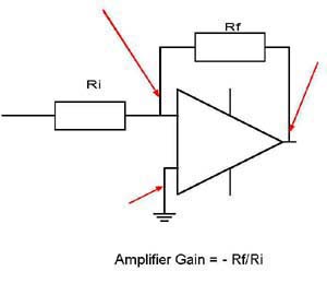
arise. See note 4 on high gain operational
amplifiers
- Kimseng, K. , Hoit,
M., Pecht, N., . Physics
of Failure of a Cruise Control Module
Microelectronics Reliability Vol 39, pp. 1423-1444
February 1999.
Kimseng et al report that
over a five year period owners of a particular type of
cruise control unit have complained of a variety of
faults : from not engaging on command, to the cruise
unexpectedly accelerating past the desired speed. They
observe that a common thread to the complaints was the
intermittent nature of the problems. More than 96% of
the reported failed modules removed from vehicles and
returned to the unnamed automobile company passed bench
tests. They report that up till the end of Oct 1997
the company in question had spent more than
$600,000 on parts alone for cruise control warranty
replacements for its 1996 vehicles and that the 1997
fleet was showing the same pattern. Note 5
Kimseng et al tested 9 cruise control modules in
all : five which had been returned two years previously
under warranty with intermittent faults that checked out
OK on bench tests and four new units straight from the
manufacturer. Their investigation did not address
vibration, but focussed on laboratory simulation of heat
and humidity conditions in the engine compartment. In
accelerated tests they demonstrated that
intermittent open and short circuits developed in a
manner that appeared to be consistent with the
service reports of intermittent faults. Both
returned and new units demonstrated two similar failure
mechanisms : (1) high resistance fretting between
separable interconnects and (2) PCB shorting from
humidity and contaminants. Both failure mechanisms
vanished after a while once the cruise control module
was removed from the test oven and had been allowed
to 'sit' for an extended period. The authors
expressed the opinion that : "It is possible that some
combination of these failure mechanisms is causing the
CCM failures and could explain the runaway acceleration
especially if the power line shorts with the motor
line."
The results of these two investigations suggest the
possibility of several inherent modes of failure within
cruise control modules that can be initiated by the
occurrence of open and short circuits on the PCB or at the
board connectors. The findings of both reports
appear to match anecdotal field reports that cruise
control fault events appear to be random and intermittent
and are not easily identifiable afterwards and sometimes
occur when the cruise control is not engaged.
From a control system point of view, intermittent
open or short circuits on the control module PCB suggest
the following possibilities:
- open-circuited feedback resistors in a high gain
amplifier that may saturate the amplifier;
- open circuits leading to disconnection of clamping
or biassing circuits resulting in the change of state
of one or more logic gates or amplifying elements;
- leakage currents that charge up the integrating
capacitor of a P & I controller and may
drive it into saturation;
- pull down resistors on logic inputs which
fail to do their job and which make logic inputs
sensitive to stray RF inputs;
- leakage of charge to or from voltage reference
capacitors that may cause errors in the speed
reference voltage(s) of the cruise control module.
If a single intermittent fault occurs on a printed circuit
board, then there is a possibility that this will cause a
false, or rogue control signal that will instruct the
throttle to open. In other words, a single fault in the
PCB in the wrong place may cause sudden acceleration.
There is therefore no need to postulate, as the NHTSA do,
a requirement for concurrent multiple intermittent faults
before a sudden acceleration incident could occur. A
single fault at a critical point within the cruise control
module might well be sufficient. Arguments
that suggest that two or more simultaneous faults
are "virtually impossible" lose most of their force when
it is realised that a single internal fault in a critical
place may be all that is necessary.
The picture is now becoming clearer. (1) Some of the
electronic circuits used in automobile cruise control
are high impedance, sensitive circuits that can
potentially suffer from leakage because of the
harsh environment in which they work. (2) the electronic
circuits are vulnerable not only to leakage but to
intermittent faults (open and short circuits) developing
as a result of either the ingress of moisture and
pollution or vibration, separately or in combination (3)
cracks in PCB tracks may cause the characteristics of
certain functional elements of the circuit to change
intermittently from one state to another (4) the results
of (1), (2), or (3) may change the characteristics of
the cruise control module sufficiently to qualify as an
intermittent fault condition.
Measures can be taken to minimise the likelihood of
internal intermittent faults, but they cannot be
eliminated altogether. When intermittent internal faults
occur, there is a possibility that they may cause
the throttle actuator to operate, without there
necessarily being a fault in the external control and
interlock logic. There is no guarantee that the
fault diagnosis systems currently in use will detect
internal intermittent faults.
Since the RoHS Directive was adopted by the EU in
February 2003, lead free solders have now become the
norm. However, lead free solders are sensitive to tin
whisker formation. These very fine whiskers, much finer
than the finest human hair, can form intermittent fault
paths between printed ciruit tracks that can momentarily
carry high currents. They rarely leave a significant
trace behind them afterwards. For further reading on
this subject see the NASA website at http://nepp.nasa.gov/whisker/background/index.htm
Water ingress
There can be little doubt that moisture ingress has
been the cause of some sudden accelerations, the
incidents in a Proton Waja in Malaysia mentioned earlier
being but one example. Sudden accelerations in car
washes seems to have affected Cherokee and Grand
Cherokee Jeeps in particular. The International
Car Wash Association has alerted its members to the
danger of vehicles suddenly accelerating during or after
the car washing process on a number of occasions. As
long ago as September 1988 the ICA advised vehicle
handlers: "Car wash employees should be constantly
reminded to turn off the ignition key when handling a
runaway automobile, when the natural tendency is to put
both feet on the brakes and push as hard as
possible. Simply reaching down and turning off the
ignition will minimize the damage in collisions and
runaways." In 2003 the ICA issued a reminder reminder
to members to report sudden acceleration
incidents so that they could continue to monitor the
situation and be prepared for future actions. In 2006
the ICA issued a revised advisory
notice in an attempt to minimise the risk
of sudden accelerations with Cherokee and Grand Cherokee
Jeeps. On June 13th 2006 Connecticut's Attorney General
Richard Blumenthal and State Representative Patricia
Widlitz called upon NHTSA to investigate sudden
acceleration problems in late model Jeep Grand
Cherokees, saying that NHTSA should require Daimler-Chrysler to
provide all information concerning sudden or
unexpected accelerations, and request information from
car wash owners, auto repairers and insurance
companies.
"The rate and
severity of these sudden acceleration incidents
suggest a severe structural flaw - certainly more than
simple coincidence," Blumenthal said. "These incidents
- in one case killing a Connecticut man - call for
aggressive and vigorous action to prevent another
needless, preventable tragedy. No safety official can
be neutral: a full-gear federal investigation is
vital."
Widlitz said, "It
is imperative that the National Highway Transportation
Safety Administration immediately launch an
investigation into the Jeep Grand Cherokee sudden
acceleration incidents. How many deaths and injuries
must the public endure before this issue gets serious
attention?"
Two days later On June15 2006 , a
52-year-old employee, who had worked at Thunderbird
Car Wash for the past 12 years, got into a 2006 Jeep —
with less than 4,000 miles on it — to drive it off the
conveyor. When he put the car in "drive," it
accelerated out of the tunnel, smashed the open door
of a Cadillac, squeezed between two other cars, jumped
a curb and was about 75 feet down a street before he
brought it under control. Report
in Carwash News For further
reading, Doug Newman a New England car wash owner has
had several sudden acceleration incidents in car washes
that he owns and has gathered a considerable body of
information together on his website at http://jeepsua.googlepages.com/home
Sayler, Bizzak and Nocivelli in their Formal
Petition
to
the
National
Highway
Traffic
Safety
Administration
Re.
1991-1995 Jeep Cherokee and Grand Cherokees
(2002) identified the 60 pin connector to the
Power Control Module (PCM), as a point where water
ingress could potentially cause the cruise control to
malfunction. Although this work relates to a specific
PCM and cruise control configuration, nevertheless it
demonstrates that multipin connectors have the potential
for developing sneak circuits that may cause
malfunctions. Multiple parallel faults become a distinct
possibility at the connector interface. This study puts
the incidence of sudden accelerations in Jeep Cherokee
and Grand Cherokees in the context of lesser rates with
other vehicles - they make the case that this shows that
sudden accelerations are vehicle-related rather than
driver related.
Possible Effects of
Electromagnetic Interference (EMI)
The effects of electromagnetic interference (EMI)
on sensitive electronic circuitry should always be
considered as a possible contributory factor to
malfunction. For example, the 1995 NASA Report
on
Electronic
Systems Failures and Anomalies Attributed to
Electromagnetic Interference refers to the
following:
- 8 NASA pre-flight case histories;
- 7 NASA in-flight case histories;
- 17 case histories involving aircraft, ships
and automobiles;
- 29 incidents where electronic devices carried onto
aircraft by passengers have interfered with aircraft
equipment;
- 4 case histories involving medical equipment,
such as an ambulance radio interfering with a heart
monitor/defibrillator and police, fire, or CB
transmitters causing runaway electric
wheelchairs.
The NASA Report says that when Mercedes Benz first
equipped their automobiles with Automatic Braking Systems
(ABS) these vehicles had severe braking problems along a
certain stretch of the German autobahn. The brakes were
affected by a nearby radio transmitter when vehicles
applied them on a curved section of the autobahn. A
short-term solution used was to erect a metal mesh screen
alongside the roadway to attenuate the Electromagnetic
Interference and enable the brakes to function
properly.
There is anecdotal evidence to suggest that, for
example, on-board mobile amateur radio equipment, if not
properly installed, may upset automobile cruise
control circuits. However, generally speaking, for
external RFI, the vehicle engine compartment will act as
a Faraday cage and should provide a fairly high degree
of screening.
When it comes to consider EMI generated within the
automobile engine compartment the situation is very
different. The most potent sources are probably
:
Whether EMI will have any effect on the electronics
will depend (1) on how effective the screening measures
are in the first place (2) whether those measures remain
effective over the working life of the vehicle. In the
presence of RFI, which will be particularly strong in the
case of spark ignition engines, a poor earth, a broken
screen, a high resistance connector etc., may be all that
is needed to allow the electronics to be subjected to an
unacceptably high level of transient disturbance, with the
potential for causing malfunctions in logic and motor
driver circuits. [A factor that needs to be taken into
consideration in most vehicles is the use of common
ground earth returns through the vehicle body, rather than
separate returns directly to the battery negative
terminal. Transient high currents generated by one
component may cause a local ground lift
at its grounding point which may affect other components
if grounded at the same point. This is particularly the
case where, after some years, the contact resistance at
the grounding point in question has risen due to the
effects of corrosion.]
Many throttle actuators now use small stepper
motor drives, which are driven by means a series of
control pulses originating in the cruise control module
or the engine control module (PCM). In the event of
stray RF derived pulses appearing at the input of the
stepper motor driver circuit, particularly if a logic
hold-down resistor should go open-circuit, these may
cause a false movement that will either open or close
the throttle. Note 6
Increasingly, automobile electronics are adopting
CAN-Bus or similar multiplexing technology to enable
communication between sensors, electronic control units
and actuators. [Note 7] Whilst Bus systems have
significant advantages in terms of reduced wiring
harness weight and complexity, they may also introduce
new potential system failure modes - for example,
the "babbling idiot syndrome" where, for some
reason, the system momentarily overloads and can
no longer handle the message transfer
requirements. What is evident is that once data is
transmitted over a common network, rather than point to
point, the system design becomes critical.
It becomes necessary to consider the potential
interactions of sub-systems that, although not coupled
from a functional point of view, and although hopefully
protected from undesirable EMI interaction, may be
disrupted by communications bus overloads and other
kinds of bus malfunction should these arise.
With regard to sudden acceleration problems that may
arise with electronic throttle controls, a
presentation by Professor Todd Hubing to the National
Academy of Sciences Sudden Acceleration
Investigation Committee in July 2010 is of particular
interest and relevance. See Hubing: 'Analyzing
Unintended Acceleration and Electronic Controls' http://onlinepubs.trb.org/onlinepubs/ua/100701hubing.pdf
.
Summarising
- Cruise control Patent literature suggests that it
has been known since 1976 that surface leakage in high
impedance circuits, particularly in sample and hold
circuits, may cause single-point-fault modes
that can result in excessive vehicle accelerations.
- The work of Gunnerhead (1988) has shown that for
one particular kind of analog cruise control with an
electro-pneumatic actuator a single cracked track in a
PCB could cause a single-point-fault mode resulting in
two supposedly independent operational amplifiers
changing state, such as to cause the throttle to open
fully.
- The work of Kinseng et al (1999) has demonstrated
that intermittent open and short circuit faults on
cruise control system printed circuit boards can be
reproduced in accelerated laboratory tests and that if
the boards are allowed to sit for a while the faults
disappear. Their view is that : "It is possible that
some combination of these failure mechanisms is
causing the CCM failures and could explain the runaway
acceleration especially if the power line shorts with
the motor line."
These three sources consistently point to the possibility
of single-point-fault modes occurring within the cruise
control module that have the potential to cause the
throttle to move to the fully open position.
Particular implementations of cruise control might be
more, or less susceptible to the same kinds of problem.
The incidence of failure will be largely dependent on
how well the particular manufacturer anticipates the
whole gamut of possible failure modes, internal and
external, and incorporates measures to prevent their
occurrence in his designs.
None of these three sources specifically mention the
possible effects of RFI. However, in my view, depending
on the particular type of cruise control unit used, RFI
from the ignition and/or starter motor, or mechanically
induced RFI caused by intermittent speed
sensor connections, might well be factors in causing
system malfunction.
One manufacturer places the cruise control module behind
an additional bulkhead within the engine compartment,
which rather suggests he is taking a "better safe than
sorry" approach by raising the level of protection against
both RFI and pollutants.
In my opinion, Hubing's work on analysing unintended
acceleration and electronic controls (July 2010) mentioned
above represents a significant advance in the state of the
art regarding the understanding the phenomenon. I would
suggest that anyone wanting to improve their own
understanding of the underlying issues should read his presentation
to the NAS carefully. |