Return to Antony Anderson's website                                                                                                                View/Sign Visitors Book
0:Cruise Control Home
1:Introduction
2:What isCruise Control?
3:Principles
4:Functional aspects
5:What is Sudden Acceleration?
6:Incidence & Examples
7:Internal 
failure mechanisms
8:Discussion of Failure Mechanisms
9:Links & References
9.5: SAI by manufacturer
Sudden Acceleration NEWS
A Note on Automobile Cruise Control Faults and Sudden Acceleration [or Unintended Acceleration]

by Dr Antony Anderson C.Eng FIEE

3. Cruise Control : Vehicle Speed Control :  principles of operation and implementation

The block diagram below shows the main elements of a typical cruise control system (vehicle speed control system).With a manual throttle, the cruise control uses a stand alone speed control amplifier and a servo that operates on the main throttle. With an electronic throttle, the cruise control electronics reduces to the input switches and logic, the electronic control function becomes part of the Engine Control ECU software and operates on the main throttle. From a functional point of view, the cruise control system remains the same with either a manual or electronic throttle.

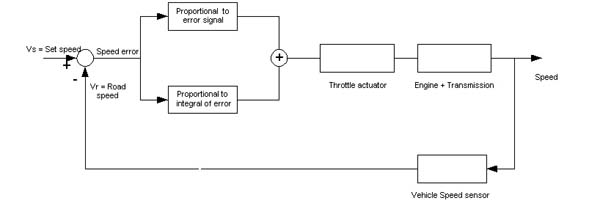
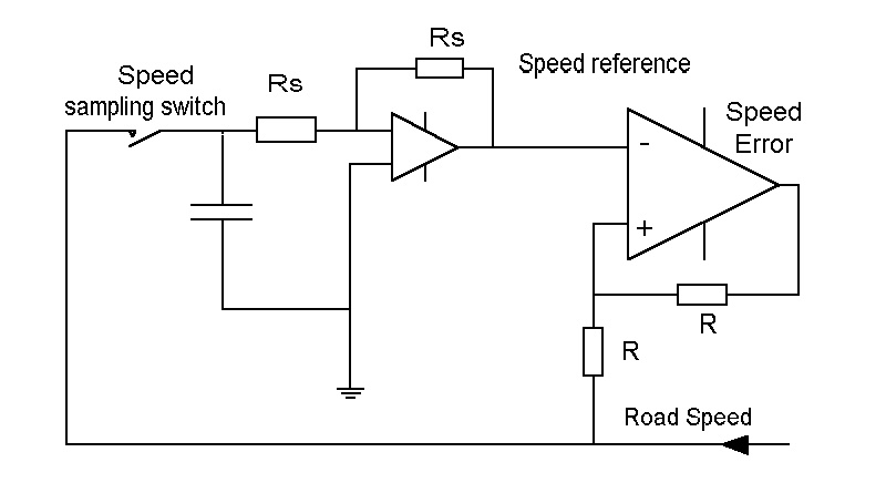
A signal proportional to road speed is fed back and compared with a set speed reference to give a speed error signal that is used to control throttle position, and hence engine power, so as to change the speed to reduce the speed error signal to zero. In some analogue systems, the speed reference voltage is held in a sample and hold amplifier that uses a  low loss capacitor. [ Note 1].  In other systems, the speed reference voltage is stored as a binary number in a digital counter. 

Cruise control systems are well described in "Understanding Automotive Electronics" Edition 5 by William B. Ribbens Newnes 1998 ISBN 0-7506-7008-8. Further references are given in Section 9.  Analog, mixed analog/digital implementations  and fully digital implementations of cruise control systems are functionally similar, although designs may may look very different.

The main variations in cruise control system can be dealt with under three headings relating to: the method of throttle actuation;  the type of electronic control; the interlocks and safety switches used : - 

Method of throttle actuation:

  • Electropneumatic servo valve actuation (vacuum, derived from the engine inlet manifold or an electric vacuum pump, is used to provide the force via bellows);
  • Electronically controlled DC motor with a worm gear or other reduction gear drive;
  • Stepper motor with electronic control. These stepper motors are often of the very simple switched reluctance type.
Type of Electronic Control
  • Analogue + hard wired logic;
  • Digital, using a discrete cruise controller;
  • Digital cruise control function incorporated in the engine control module.
  • Digital cruise control function incorporated in the Electronic Throttle Control (ECT) and engine ECU, with electronic systems multiplexed together via typically one or more CAN-Bus systems. [Note 2]
Interlocks and safety switches
  • Various safety switch interlocks are included to prevent the cruise control system from operating when it would not be safe for it to do so.
  • The frequency of the road speed sensor is measured continuously and is compared with a reference in order to provide a logic signal that inhibits the cruise control below a predetermined road speed, typically between 20 and 30 mph.   [Note 3]
  • Circuitry is designed to disable the cruise control when, for example, slight pressure is applied to the brake pedal.
  • In some cases, a measure of protection against cruise actuator malfunction is given either by :
    • reducing the supply voltage to the actuator, except when the cruise control is "on" or
    • mechanically decoupling the actuator, except when the cruise control is "on", by means of an electromagnetic clutch.
However, although  these safety measures will tend to reduce the incidence of sudden accelerations, they cannot prevent them altogether. It is therefore essential to take the possibility of a sudden acceleration into account during the design stage and include measures outside the cruise control system that come into play when the protective measures within the system  fail. As matters currently stand, if a sudden acceleration should occur, the driver is expected to act as the ultimate fail-safe by applying the brakes against full engine power. We will discuss later whether or not it is reasonable to treat the driver as the  fail-safe for an electronic system.

 Don't forget to bookmark Section 9 Links and References before leaving this site.

0:Cruise Control Home
1:Introduction
2:What isCruise Control?
3:Principles
4:Functional aspects
5:What is Sudden Acceleration?
6:Incidence & Examples
7:Internal 
failure mechanisms
8:Discussion of Failure Mechanisms
9:Links & References
Sudden Acceleration NEWS

Please view/sign my Visitors Book
See also: Visitors Book Archive 2000-2007

Privacy statement

Notes for Section 3

Note 1: Sample and hold circuit for speed reference purposes

The figure below shows a representation of a typical sample and hold circuit feeding the speed error amplifier, as used in an analog cruise control circuit. Voltage holding capability  depends upon the storage capacitor not losing or gaining charge via a leakage path. This may be difficult to guarantee under all circumstances in an automobile environment. In order to keep down the leakage current from the capacitor, Rs must be kept very high.

typical sample
                  and hold circuit feeding the speed error amplifier


Note 2: [August 2005] Multiplexed systems. Increasingly, automobile electronic systems are multiplexed and typically use one or more CAN-Bus systems to interconnect the electronic control elements. Multiplexing does not  functionally change systems such as cruise control. However, multiplexed systems have to be designed very carefully if they are to avoid introducing additional failure modes caused by  transiently overloading the bus - sometimes called the "babbling idiot syndrome".

Note 3: [May 2009] Measurement of road speed. There are two kinds of speed measuring systems used. One is analog and produces a signal whose frequency and amplitude is proportional to road speed. The other is digital and produces a train of pulses of constant amplitude at a frequency proportional to speed. At low speeds, either type of speed measuring system is sensitive to EMI - especially mechanically induced EMI caused by an intermittent electrical contact in the sensor circuit - which can result in the generation of a false speed signal that is of much higher frequency than the road speed signal. See Reference for significance

Cruise Home


Section 3: Version 1.1 : last updated 9th July 2001
Jan 31st 2003, August 2005, May 15th 2009, August 26th 2009,July 28 2011, March 8th 2012, January 8th 2013